A large, somewhat complex, but very worthwhile undertaking!
Hans Summers G0UPL has designed a great project:
See it here: Spectrum Analyzer
I have added some some modifications:
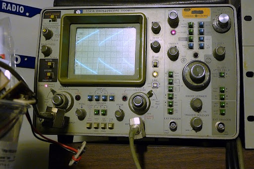
The completed analyzer triggered my HP1741A scope in 'reverse',
meaning that, as the input to the anayzer increased in frequency,
the pip on the trace would move right to left, instead of the usual left to right.
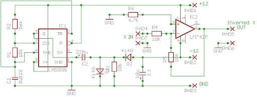
I designed and built a sweep inverter, which triggered my scope properly:
It can be seen on the GP0UPL Analyzer website page as well: Inverter
here is the schematic for the sweep inverter:
I also made a few impedence matching amplifiers using a MAX4200 amp as a buffer.

I did not use SMA connectors, I only used a lot of double ended RCA's,
resulting in my Analyzer not working past 45 MHz or so. (May need to upgrade soon!)
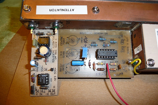
A photo of the sweep inverter attached to the anayzer's sweep generator:
And finally a photo of the original ramp from the sweep generator
and the resulting inverted ramp:
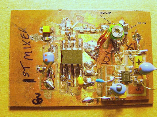
Here is the 1st Mixer / MAX4200 PCB, typical of the boards I built.
It was layed out on EAGLE CAD 5.11, laser printed onto acetate,
heat transferred to copper board and etched with ferric chloride.
The components are mostly SMT, a little messy, but it works well:
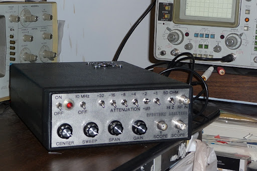
COMPLETED ANAYZER FRONT: designed with FRONT PANEL DESIGNER
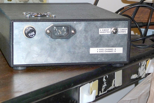
SPECTRUM ANALYZER REAR:
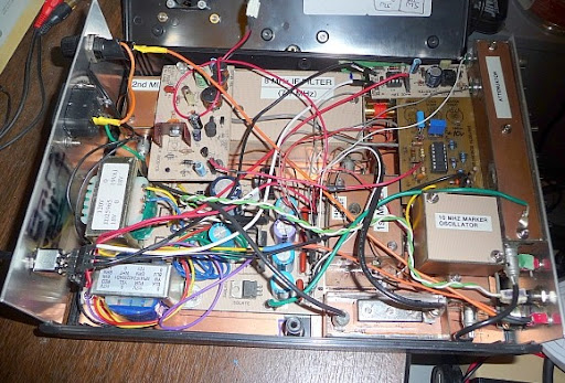
INSIDE THE PROJECT:
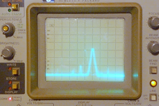
THE WORKING ANALYZER,
15 MHz INPUT WITH 10 MHz MARKERS 'ON'