Here is a very
sophisticated
and useful project for any ham radio builder or experimenter.
A direct digital synthesis VFO using two 16F628 PIC's
and an Analog Devices AD9851 for a VFO or a wide
range frequency generator.
The copper boards were fabricated using CIRCAD design software, an "iron-on" laser printed acetate sheet, then the boards were etched, drilled and tinned.
This project will be placed in a 50w homebrew ham
radio transceiver, seen in the section The Shack
PROJECT FEATURES:
Range 0 to 70 MHz by 1 Hz step.
Freq setting in 1, 10, 100Hz, 1, 10, 100KHz, 1, 10 MHz
-by using a low cost mechanical encoder with a variable tuning rate.
2 rows X 16 character LCD display.
A 4 x 3 Keypad used for easy direct freq. entry.
IF, CW, SSB offsets settings when used with Transceiver/ Receiver.
Software calibration to WWV or equivalent.
Two VFOs and split freq operation.
19 user memories, memories freq + mode (i.e. LSB/USB etc.)
All settings are held in EEPROM and are permanent (but user can change it any time).
4 Mode selection outputs: AM, CW, USB, LSB.
When operating below IF frequency, clockwise rotation of rotary encoder decreases DDS out put frequency
-but increases the display frequency. RIT operation.
Version 4.0 also has a 9 band-specific DC output for switching relays / filters
This project was designed by:
C V NIRAS / VU3CNS,
The schematics, forums, PCB designs, and HEX files
are located at:
http://www.hamradioindia.org/circuits/dds.php
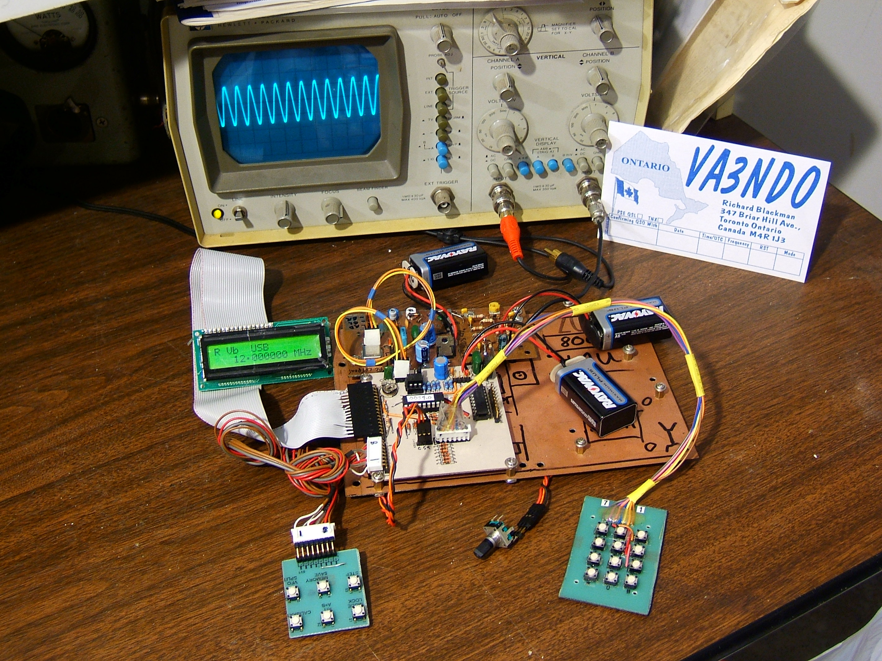
DDS VFO V4.06 in operation @ 12MHz, amplified by an AD8008 to 3v P-P.
Items of interest: direct entry keypad, shaft encoder, mode switches.
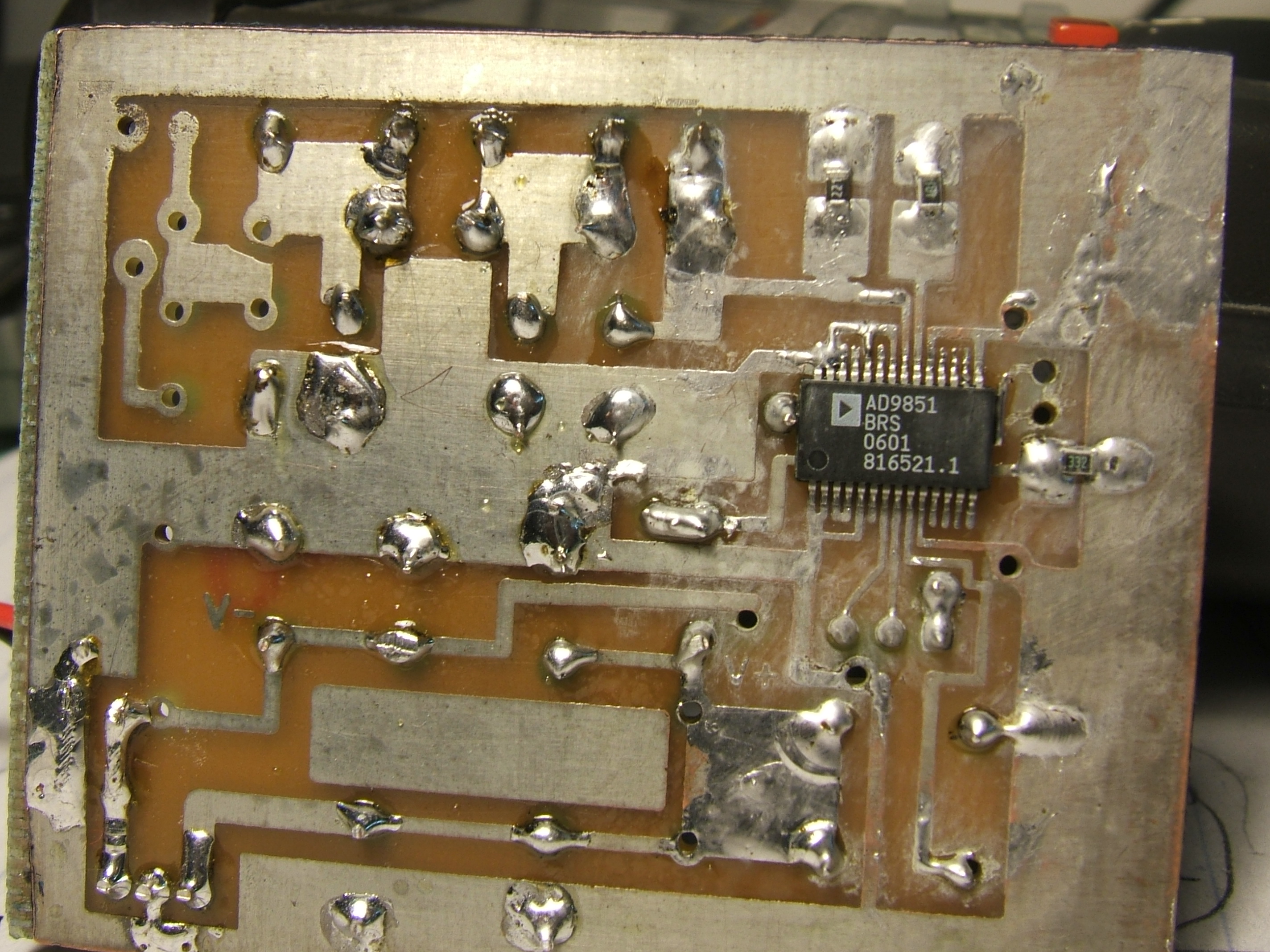
The AD9851 is on the bottom of the PCB,
I used a 16X surgical operating microscope to
help with the soldering of the surface mount pads.
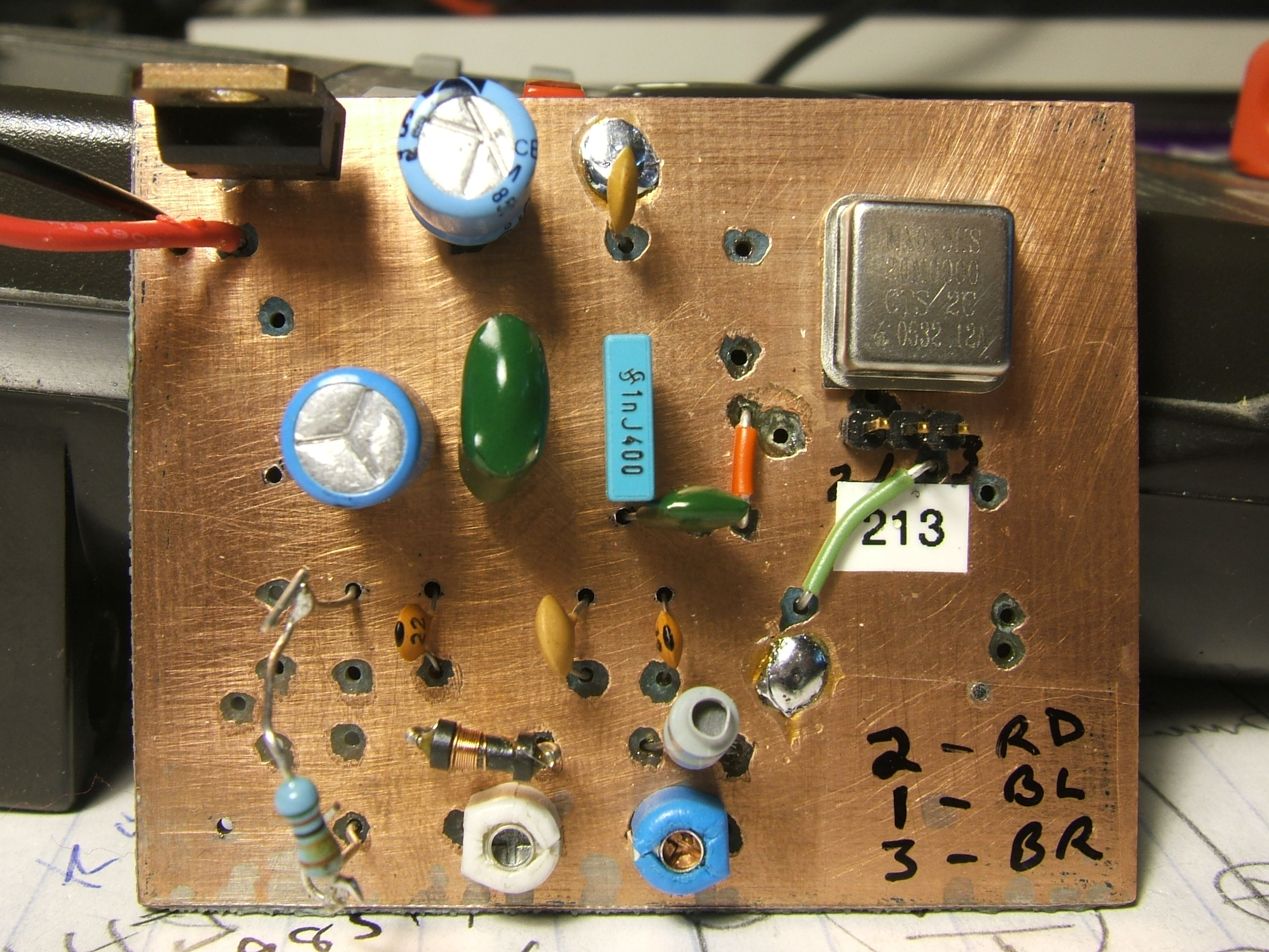
Top side of the DDS board showing crystal oscillator
and low pass filter section prior to output. The three pins
below the oscillator are the connection to the PIC board.
50 ohm resistor temporarily in place for testing purposes.
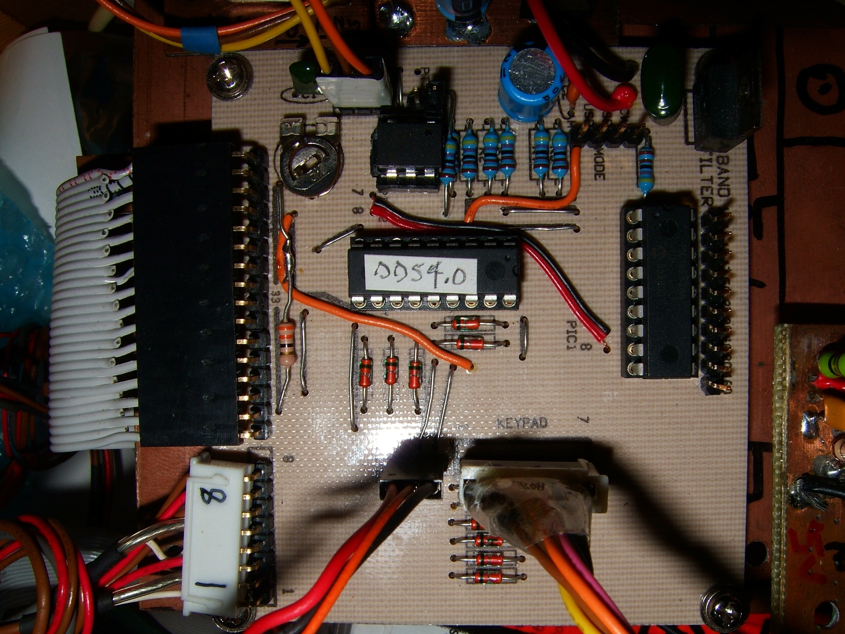
This is the control board, with 2 16F628's
There are leads going to the LCD, the encoder, the keypad, the function pad, the DDS board and power.
The header on the right side is for the band filter switches.
The DDS VFO schematic specifies a mechanical rotary shaft encoder, but here is a an interface for an optical shaft encoder. This encoder also has
a push momentary switch which is used to adjust the tuning steps. Nice.
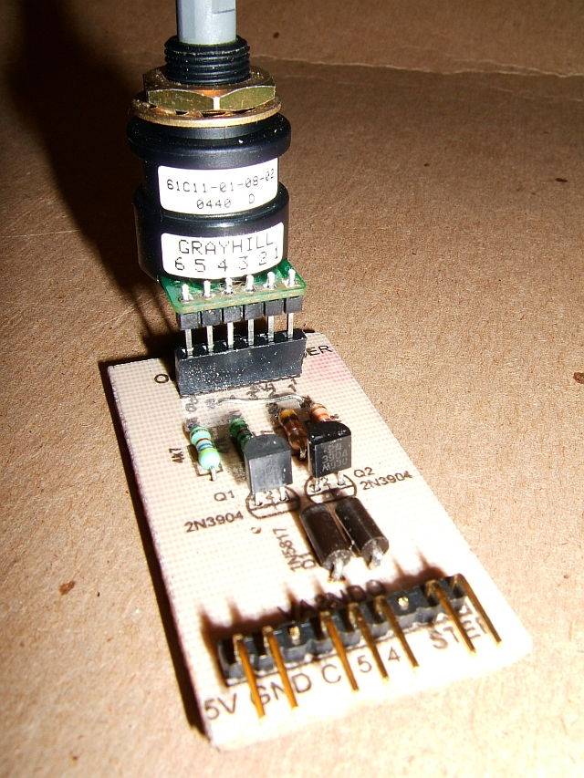
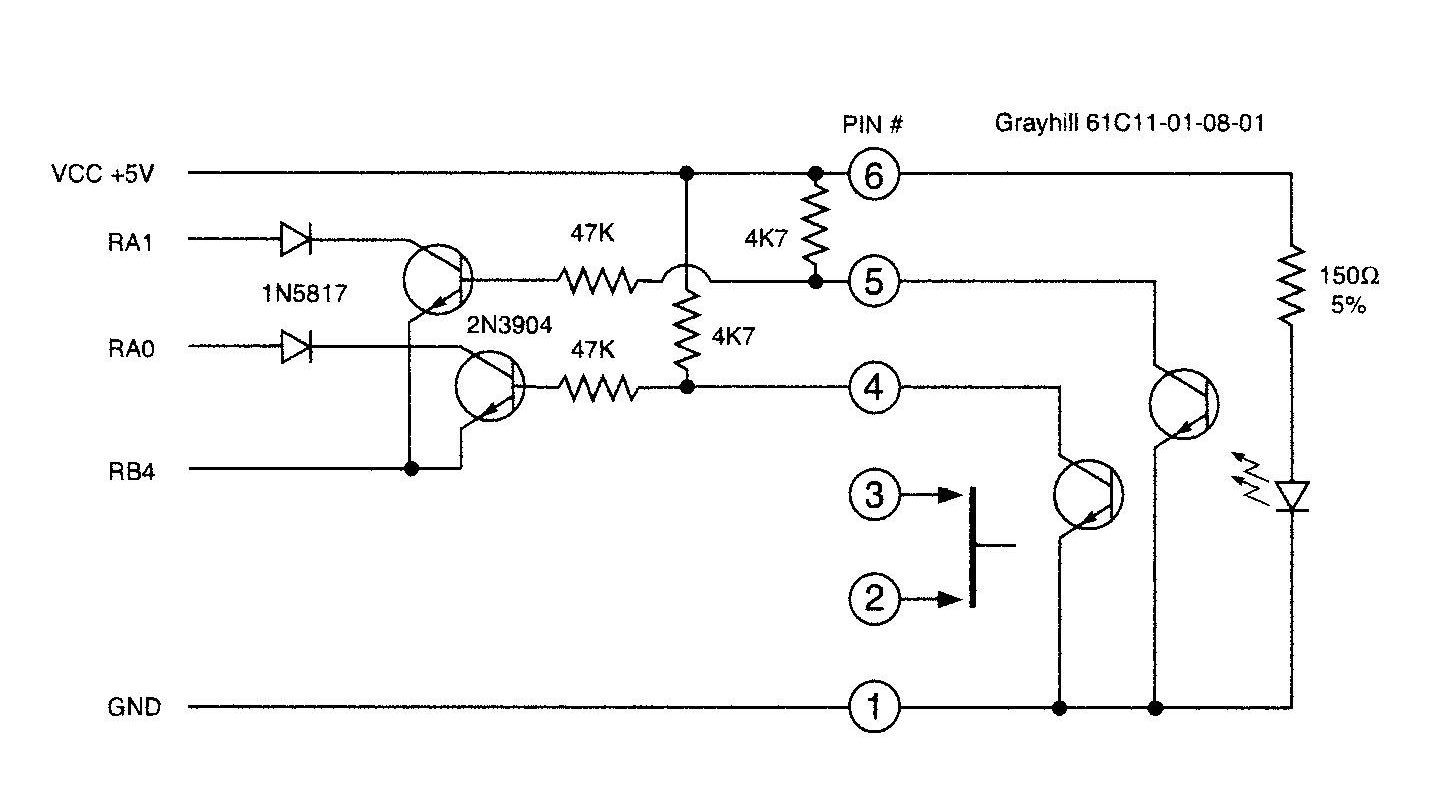
Here is a schematic for the interface,
design by Glenn Fawcett, Vancouver BC :
A direct digital synthesis VFO using two 16F628 PIC's
and an Analog Devices AD9851 for a VFO or a wide
range frequency generator.
The copper boards were fabricated using CIRCAD design software, an "iron-on" laser printed acetate sheet, then the boards were etched, drilled and tinned.
This project will be placed in a 50w homebrew ham
radio transceiver, seen in the section The Shack
PROJECT FEATURES:
Range 0 to 70 MHz by 1 Hz step.
Freq setting in 1, 10, 100Hz, 1, 10, 100KHz, 1, 10 MHz
-by using a low cost mechanical encoder with a variable tuning rate.
2 rows X 16 character LCD display.
A 4 x 3 Keypad used for easy direct freq. entry.
IF, CW, SSB offsets settings when used with Transceiver/ Receiver.
Software calibration to WWV or equivalent.
Two VFOs and split freq operation.
19 user memories, memories freq + mode (i.e. LSB/USB etc.)
All settings are held in EEPROM and are permanent (but user can change it any time).
4 Mode selection outputs: AM, CW, USB, LSB.
When operating below IF frequency, clockwise rotation of rotary encoder decreases DDS out put frequency
-but increases the display frequency. RIT operation.
Version 4.0 also has a 9 band-specific DC output for switching relays / filters
This project was designed by:
C V NIRAS / VU3CNS,
The schematics, forums, PCB designs, and HEX files
are located at:
http://www.hamradioindia.org/circuits/dds.php
DDS VFO V4.06 in operation @ 12MHz, amplified by an AD8008 to 3v P-P.
Items of interest: direct entry keypad, shaft encoder, mode switches.
The AD9851 is on the bottom of the PCB,
I used a 16X surgical operating microscope to
help with the soldering of the surface mount pads.
Top side of the DDS board showing crystal oscillator
and low pass filter section prior to output. The three pins
below the oscillator are the connection to the PIC board.
50 ohm resistor temporarily in place for testing purposes.
This is the control board, with 2 16F628's
There are leads going to the LCD, the encoder, the keypad, the function pad, the DDS board and power.
The header on the right side is for the band filter switches.
The DDS VFO schematic specifies a mechanical rotary shaft encoder, but here is a an interface for an optical shaft encoder. This encoder also has
a push momentary switch which is used to adjust the tuning steps. Nice.
Here is a schematic for the interface,
design by Glenn Fawcett, Vancouver BC :